

Recreating Nanite: Visibility buffer
Matching commits:
Table of contents:
- Adding the visibility buffer passes
- First test: drawing the Standford Bunny in the visibility buffer
- Depth testing
- That’s it?
Adding the visibility buffer passes
Carrot has a render graph system for its rendering. There is a default render graph implemented inside CarrotRenderingPipeline.cpp, which already has gbuffer + lighting passes.
I am adding multiple passes between the gbuffer and the lighting pass. The goal is first to write the visibility buffer (hardware & software rasterization), and the material pass will then write to the GBuffer directly.
Here’s what the passes will return:
struct VisibilityPassData {
    PassData::GBuffer gbuffer; // All GBuffer information (albedo, positions, normals, etc.)
    Render::FrameResource visibilityBuffer; // The visibility buffer
};
The very first step is to simply add the render passes, without any modification of the GBuffer. Here’s the first version of my code:
struct VisibilityBufferRasterizationData {
    Render::FrameResource visibilityBuffer;
    Render::FrameResource depthStencil;
};

const VisibilityBuffer::VisibilityPassData& VisibilityBuffer::addVisibilityBufferPasses(Render::GraphBuilder& graph, const Render::PassData::GBuffer& gBufferData, const Render::TextureSize& framebufferSize) {
    // Add the hardware rasterization pass
    auto& rasterizePass = graph.addPass<VisibilityBufferRasterizationData>("rasterize visibility buffer",
        [this, framebufferSize](Render::GraphBuilder& builder, Render::Pass<VisibilityBufferRasterizationData>& pass, VisibilityBufferRasterizationData& data) {
            vk::ClearColorValue clearVisibilityValue{ (std::uint32_t)0, (std::uint32_t)0, (std::uint32_t)0, (std::uint32_t)0 };
            // Declare the visibility buffer texture
            data.visibilityBuffer = builder.createStorageTarget("visibility buffer", vk::Format::eR64Uint, framebufferSize, vk::AttachmentLoadOp::eClear,
                                                                clearVisibilityValue);
            // we are going to use the depth buffer of the "regular" GBuffer pass
            data.depthStencil = builder.write(gBufferData.depthStencil, vk::AttachmentLoadOp::eLoad, vk::ImageLayout::eDepthStencilAttachmentOptimal, vk::ImageAspectFlagBits::eDepth | vk::ImageAspectFlagBits::eStencil);
        },
        [this](const Render::CompiledPass& pass, const Render::Context& frame, const VisibilityBufferRasterizationData& data, vk::CommandBuffer& cmds) {
            ZoneScopedN("CPU RenderGraph visibility buffer rasterize");
            TracyVkZone(GetEngine().tracyCtx[frame.swapchainIndex], cmds, "visibility buffer rasterize");

            // no-op at this point
        }
    );

    // Take visibility buffer as input and render materials to GBuffer
    auto& materialPass = graph.addPass<VisibilityPassData>("visibility buffer materials",
        [this, &gBufferData, &rasterizePass](Render::GraphBuilder& builder, Render::Pass<VisibilityPassData>& pass, VisibilityPassData& data) {
            data.gbuffer.writeTo(builder, gBufferData);
            data.visibilityBuffer = builder.read(rasterizePass.getData().visibilityBuffer, vk::ImageLayout::eShaderReadOnlyOptimal);
        },
        [this](const Render::CompiledPass& pass, const Render::Context& frame, const VisibilityPassData& data, vk::CommandBuffer& cmds) {
            // no-op for now
        }
    );

    return materialPass.getData();
}
Currently, nothing will be drawn to the visibility buffer texture.
ZoneScopedN and TracyVkZone are used for profiling render passes, both on CPU and on GPU.
These passes do not modify the GBuffer, but are properly added to the global render graph:
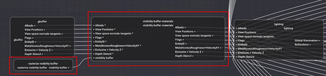
Render graphs debug view inside the engine. You can see the two visibility buffer passes being present in the graph. “gbuffer” is the regular rasterization of meshes to a GBuffer.
First test: drawing the Standford Bunny in the visibility buffer
To test whether the visibility buffer is filled correctly, I need to draw something into it. I have selected the classic Standford Bunny for this test.
I also need a way to tell my engine whether a given mesh will be rendered via rasterization to the GBuffer directly, or whether I want to use the visibility buffer. To this end, I have added an option per mesh of a model to select whether to use Virtualized Geometry. I don’t know yet if it will stay that way, but I have to start somewhere.
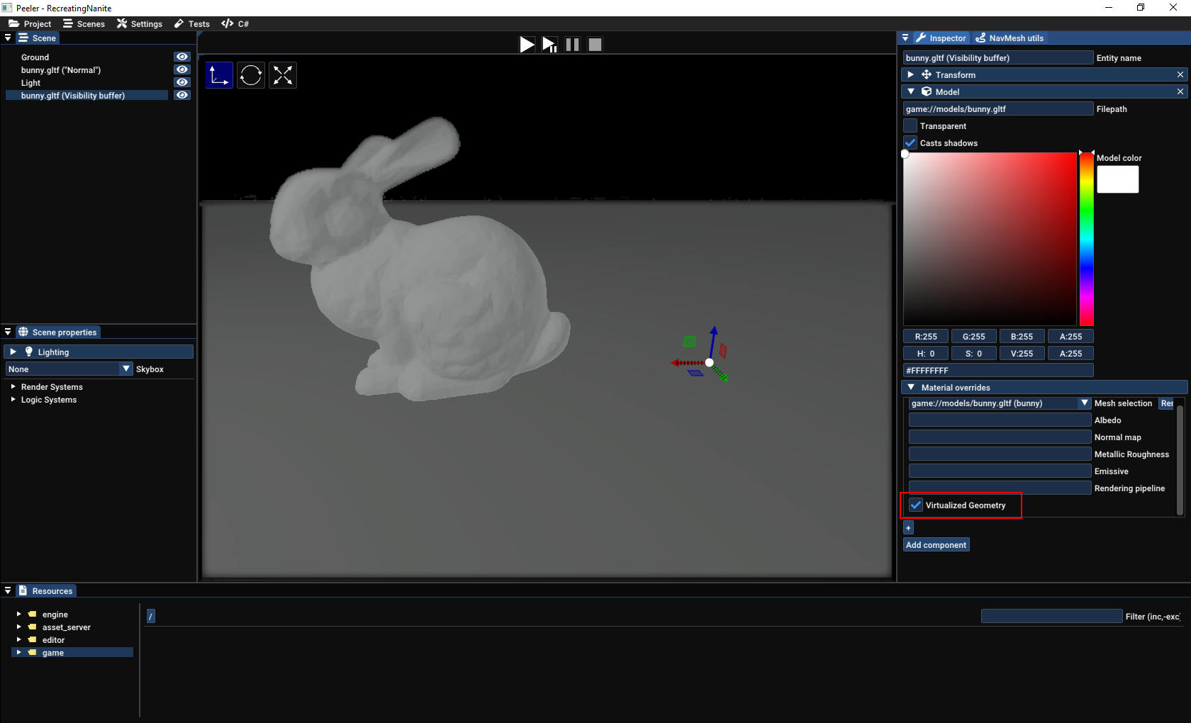
Virtualized Geometry checkbox inside the editor. In the scene, there are two bunnies, one rendered to the GBuffer directly (left), and one which will be rendered to the visibility buffer (right, and invisible for now).
Writing triangles to a U64Int image
We first need to clear the storage image used for the visibility buffer, so inside the recording of commands for the rasterize visibility buffer pass:
// get the visibility buffer texture for this frame
auto& texture = pass.getGraph().getTexture(data.visibilityBuffer, frame.swapchainIndex);

// setup the compute pipeline to clear the buffer (shader presented below)
auto clearPipeline = renderer.getOrCreatePipelineFullPath("resources/pipelines/compute/clear-visibility-buffer.json");
renderer.bindStorageImage(*clearPipeline, frame, texture, 0, 0,
                            vk::ImageAspectFlagBits::eColor, vk::ImageViewType::e2D, 0, vk::ImageLayout::eGeneral);
const auto& extent = texture.getSize();
const std::uint8_t localSize = 32;
std::size_t dispatchX = (extent.width + (localSize-1)) / localSize;
std::size_t dispatchY = (extent.height + (localSize-1)) / localSize;

// bind pipeline & dispatch compute shader
clearPipeline->bind({}, frame, cmds, vk::PipelineBindPoint::eCompute);
cmds.dispatch(dispatchX, dispatchY, 1);

// barrier to ensure we don't try to use the visibility buffer before it is cleared
vk::MemoryBarrier2KHR memoryBarrier {
        .srcStageMask = vk::PipelineStageFlagBits2KHR::eComputeShader,
        .srcAccessMask = vk::AccessFlagBits2KHR::eShaderWrite,
        .dstStageMask = vk::PipelineStageFlagBits2KHR::eFragmentShader,
        .dstAccessMask = vk::AccessFlagBits2KHR::eShaderRead,
};
vk::DependencyInfoKHR dependencyInfo {
        .memoryBarrierCount = 1,
        .pMemoryBarriers = &memoryBarrier,
};
cmds.pipelineBarrier2KHR(dependencyInfo);
And here’s the simple accompagning compute shader, which simply writes 0 in the entire image:
// declare usage of uint64_t type
#extension GL_EXT_shader_explicit_arithmetic_types_int64 : enable
#extension GL_EXT_shader_image_int64 : enable

layout (local_size_x = 32) in;
layout (local_size_y = 32) in;

layout(r64ui, set = 0, binding = 0) uniform writeonly u64image2D outputImage;

void main() {
    const ivec2 coords = ivec2(gl_GlobalInvocationID);

    const ivec2 size = imageSize(outputImage);

    if(coords.x >= 0
    && coords.y >= 0
    && coords.x < size.x
    && coords.y < size.y) {
        imageStore(outputImage, coords, u64vec4(0ul));
    }
}
Finally, we want to record Render::Packets which want to render during the VisibilityBuffer pass:
// setup pipeline (described below)
auto pipeline = renderer.getOrCreatePipelineFullPath("resources/pipelines/visibility-buffer.json");
renderer.bindStorageImage(*pipeline, frame, texture, 1, 0,
                            vk::ImageAspectFlagBits::eColor, vk::ImageViewType::e2D, 0, vk::ImageLayout::eGeneral);

// Record all render packets (~= draw commands) with the tag "VisibilityBuffer"
frame.renderer.recordPassPackets(Render::PassEnum::VisibilityBuffer, pass.getRenderPass(), frame, cmds);
The visibility-buffer pipeline is a graphics pipeline with the following systems:
- No culling
- No blending
- Depth write & depth test enabled
visibility-buffer.vertex.glslandvisibility-buffer.fragment.glslshaders
The vertex input is the same as what is used in the rest of the engine. For now, I will use the same layout. Using the same layout is more convenient, because I can change the pipeline used for rendering my test meshes, without having to process their vertex data to conform to a new layout. Here’s the layout:
struct Vertex {
    /// World position of the vertex
    alignas(16) glm::vec4 pos;

    /// RGB color
    alignas(16) glm::vec3 color;

    /// Vertex Normal
    alignas(16) glm::vec3 normal;

    /// Vertex tangent, W is the sign of the bitangent (B = tangent.w * cross(N, T) with N,T orthonormalized)
    alignas(16) glm::vec4 tangent;

    /// UV coordinates
    alignas(16) glm::vec2 uv;
};
Here, pos is the only attribute we will need for writing to the visibility buffer.
The vertex shader transforms the input vertices from mesh-space/local-space to NDC coordinates, based on the camera. So nothing fancy:
#include <includes/camera.glsl>
// defines a cbo object which contains mat4 "view" and "jittedProjection" corresponding to the camera used for rendering
DEFINE_CAMERA_SET(0)

// Per vertex
layout(location = 0) in vec4 inPosition;

// Per instance
layout(location = 7) in mat4 inInstanceTransform;

layout(location = 0) out vec4 ndcPosition;

void main() {
    mat4 modelview = cbo.view * inInstanceTransform;
    vec4 viewPosition = modelview * inPosition;

    ndcPosition = cbo.jitteredProjection * viewPosition;
    gl_Position = ndcPosition;
}
Vertex shader
The fragment shader is a bit more interesting, because it is where we are going to write the triangles! The idea:
- Find the proper pixel coordinate
- Compute the value we want for the visibility buffer
- Use
imageAtomicMaxto write to the visibility buffer- We cannot output the value directly inside the fragment shader because in GLSL fragment shaders cannot output a U64 value (point 5 at the bottom of the document). However, you CAN store U64 values into images directly via
imageStoreandimageAtomicXXX.
Therefore, we will need to encode the depth in the upper bits of the value, in a way to ensure the closest triangle end up with their value written inside the buffer at the end of rendering. (see section a bit further below)
- We cannot output the value directly inside the fragment shader because in GLSL fragment shaders cannot output a U64 value (point 5 at the bottom of the document). However, you CAN store U64 values into images directly via
#extension GL_EXT_shader_explicit_arithmetic_types_int64 : require
#extension GL_EXT_shader_atomic_int64 : require
#extension GL_EXT_shader_image_int64 : require

layout(r64ui, set = 1, binding = 0) uniform u64image2D outputImage;

layout(location = 0) in vec4 ndcPosition;

void main() {
    ivec2 imageSize = imageSize(outputImage);

    vec4 ndc = ndcPosition;
    ndc.xyz /= ndc.w;
    vec2 pixelCoordsFloat = (ndc.xy + 1.0) / 2.0 * imageSize;

    ivec2 pixelCoords = ivec2(pixelCoordsFloat);
    uint64_t value = gl_PrimitiveID; // <------- value written inside buffer
    imageAtomicMax(outputImage, pixelCoords, value);
}
Fragment shader
Until we encode the depth, we will use gl_PrimitiveID to write the current triangle index into the buffer.
Visualisation
At this point, we have absolutely no way to know if the contents of the visibility buffer are correct. The buffer is a U64 image, and we will need a custom pass to render a RGBA texture that will be more easily readable.
For this, I use a fullscreen render with the following shader:
#extension GL_EXT_shader_explicit_arithmetic_types_int64 : enable
#extension GL_EXT_shader_explicit_arithmetic_types_int8 : enable
#extension GL_EXT_shader_image_int64 : enable

#include <includes/lighting_utils.glsl>

layout(r64ui, set = 0, binding = 0) uniform u64image2D inputImage;

layout(location = 0) in vec2 uv;
layout(location = 0) out vec4 outColor;

ivec2 uvToPixels(vec2 uv) {
    ivec2 inputImageSize = imageSize(inputImage);
    return ivec2(uv * inputImageSize);
}

vec4 colors[] = {
    vec4(0,0,0,1),
    vec4(189.0f / 255.0f, 236.0f / 255.0f, 182.0f / 255.0f, 1.0f),
    vec4(108.0f / 255.0f, 112.0f / 255.0f,  89.0f / 255.0f, 1.0f),
    vec4(203.0f / 255.0f, 208.0f / 255.0f, 204.0f / 255.0f, 1.0f),
    vec4(250.0f / 255.0f, 210.0f / 255.0f,  01.0f / 255.0f, 1.0f),
    vec4(220.0f / 255.0f, 156.0f / 255.0f,   0.0f / 255.0f, 1.0f),
    vec4( 42.0f / 255.0f, 100.0f / 255.0f, 120.0f / 255.0f, 1.0f),
    vec4(120.0f / 255.0f, 133.0f / 255.0f, 139.0f / 255.0f, 1.0f),
    vec4(121.0f / 255.0f,  85.0f / 255.0f,  61.0f / 255.0f, 1.0f),
    vec4(157.0f / 255.0f, 145.0f / 255.0f,  01.0f / 255.0f, 1.0f),
    vec4(166.0f / 255.0f,  94.0f / 255.0f,  46.0f / 255.0f, 1.0f),
    vec4(203.0f / 255.0f,  40.0f / 255.0f,  33.0f / 255.0f, 1.0f),
    vec4(243.0f / 255.0f, 159.0f / 255.0f,  24.0f / 255.0f, 1.0f),
    vec4(250.0f / 255.0f, 210.0f / 255.0f,  01.0f / 255.0f, 1.0f),
    vec4(114.0f / 255.0f,  20.0f / 255.0f,  34.0f / 255.0f, 1.0f),
    vec4( 64.0f / 255.0f,  58.0f / 255.0f,  58.0f / 255.0f, 1.0f),
    vec4(157.0f / 255.0f, 161.0f / 255.0f, 170.0f / 255.0f, 1.0f),
    vec4(164.0f / 255.0f, 125.0f / 255.0f, 144.0f / 255.0f, 1.0f),
    vec4(248.0f / 255.0f,   0.0f / 255.0f,   0.0f / 255.0f, 1.0f),
    vec4(120.0f / 255.0f,  31.0f / 255.0f,  25.0f / 255.0f, 1.0f),
    vec4( 51.0f / 255.0f,  47.0f / 255.0f,  44.0f / 255.0f, 1.0f),
    vec4(180.0f / 255.0f,  76.0f / 255.0f,  67.0f / 255.0f, 1.0f),
    vec4(125.0f / 255.0f, 132.0f / 255.0f, 113.0f / 255.0f, 1.0f),
    vec4(161.0f / 255.0f,  35.0f / 255.0f,  18.0f / 255.0f, 1.0f),
    vec4(142.0f / 255.0f,  64.0f / 255.0f,  42.0f / 255.0f, 1.0f),
    vec4(130.0f / 255.0f, 137.0f / 255.0f, 143.0f / 255.0f, 1.0f),
};

vec4 triangleIndexToFloat(uint64_t index) {
    if(index == 0) {
        return colors[0];
    }
    return colors[uint8_t(index % 25ul + 1)];
}

void main() {
    uint64_t triangleIndex = imageLoad(inputImage, uvToPixels(uv)).r & 0xFFFFFFFFul;

    outColor = triangleIndexToFloat(triangleIndex);
}
Debug view shader
That’s a lot of code, let’s see what our bunny looks like now:
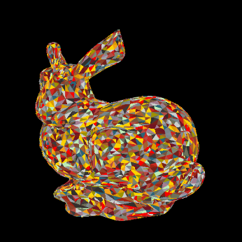
First draw into the visibility buffer!
And let’s rotate the bunny!
Depth testing is not working! 😱
Depth testing
Disaster!
By writing to the visibility buffer directly, we lost depth testing: depending on the order in which fragments are shaded, different triangles will appear in front. What we want is to write a value to the visibility buffer, which will contain both the triangle ID, and an identifier to tell whether a triangle should be in front or not.
And actually, we already have a perfect concept for this identifier: the depth value of each fragment! By encoding the depth inside the 64 bits value written to the visibility buffer, we are able to do an atomicMax on the visibility buffer to ensure we always have the closest triangle appear on top:
void main() {
    ivec2 imageSize = imageSize(outputImage);

    vec4 ndc = ndcPosition;
    if(ndc.z < 0) {
        discard;
    }

    ndc.xyz /= ndc.w;
    vec2 pixelCoordsFloat = (ndc.xy + 1.0) / 2.0 * imageSize;

    ivec2 pixelCoords = ivec2(pixelCoordsFloat);
    // reverse order: closest triangles win
    uint depth = 0xFFFFFFFFu - uint(double(ndc.z) * 0xFFFFFFFFu);
    // 32 high bits: depth
    // 32 low bits: triangle ID (will change in the future)
    uint low = gl_PrimitiveID & 0xFFFFFFu;
    uint64_t value = pack64(u32vec2(low, depth));
    imageAtomicMax(outputImage, pixelCoords, value);
}
Fragment shader, modified to account for depth testing
Because ndc.z is already in the range 0 to 1 for values between the near and far planes, we can simply map the range 0 -> 1, to the range 2^32 -> 0.
Fixed depth testing!
That’s it?
That will be it for this article. I initially wanted to create the material pass at the same time as the visibility buffer pass, but in the state described in this post, there is no way to uniquely identify triangles once they are written inside the visibility buffer. Therefore, there is no way to know which instance the triangle belongs to, nor which are its UVs, normals, etc.