

Recreating Nanite: The Plan
- Disclaimer: I am not an expert on virtualized geometry, and I’ve never implemented it before. So I might be wrong on how it works. Also I don’t have access to Unreal source code.
Introduction
One of the Hot-New-Things in rendering is currently Virtualized Geometry (or Nanite). I will use “Nanite” and “Virtualized Geometry” interchangeably in this post.
If you are not familiar with Nanite, here’s a quick introduction (from what I understood):
Basically, Nanite is level-of-detail (LOD) clusters + “software” rasterization.
First, generate LOD clusters for your meshes:
- Load a mesh.
- Create a hierarchy of clusters: group triangles connected in clusters (Unreal uses ~128 triangles per cluster).
- Recursively group clusters in group of 4 to create a hierarchy of clusters. In each group of clusters, a triangle reduction algorithm is applied.
- Once a new cluster is formed from the 4 clusters below in the hierarchy, split this new cluster into 2. This allows to avoid having boundaries that are locked in the entire hierarchy.
- Continue until you have a single cluster.
Then, at runtime, select the appropriate LOD for each cluster: Unreal calls it a “cut” because you are trying to find the boundary between drawn and discarded clusters, based on their size on screen.
Finally, for very tiny triangles (~1 pixel in area), Nanite rasterizes triangles itself via a compute shader, because GPUs tend to perform poorly with tiny triangles. For large or medium size triangles, Nanite simply uses regular hardware rasterization.
From Unreal Engine’s documentation: Nanite overview inside Unreal
The version of Nanite explained in its introduction paper has a few disadvantages:
- No support for alpha testing (no idea how to fix that)
- No support for transparent meshes (same as deferred rendering)
- No support for skinned meshes (I have some vague idea to support this case)
- Memory hungry
The Plan
My engine Carrot does not support LODs of any kind out-of-the-box in its current state. Therefore I want to add a LODing system, and Virtualized Geometry looks like it is fun to implement, so let’s kill two birds with one stone.
Currently I have nothing started for the implementation, but here’s the steps I have in mind:
- Visibility buffer
- Cluster generation
- LODs generation
- LODs selection
- Software rasterization (Maybe)
- Going further
Visibility buffer
Current, Carrot uses deferred rendering, with a GBuffer that looks like this:
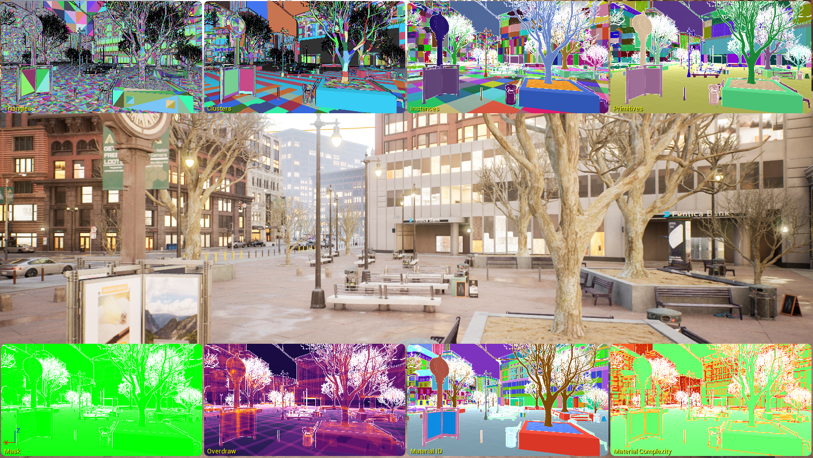
Carrot GBuffer. In order: final frame, albedo, viewspace positions, viewspace normals, viewspace tangents, roughness+metallicness, and emissive color. Motion vectors and depth not shown.
While maybe not stricly necessary, I want to decouple materials from rasterization, therefore I need to add a visibility buffer to my rendering pipeline.
The goal of the visibility buffer is to store, for each pixel:
- Its depth: Z coordinate
- Its instance index: which instance produced that pixel
- Its triangle index: a global index to know which triangle generated this pixel
One trick Nanite uses is to store this information as a single UInt64, with the higher bits representing the depth. This allows to perform an InterlockedMax (HLSL)/atomicMax (GLSL) when storing the value to do depth testing and avoid locks at the same time. This trick allows “depth testing” with compute shaders, but also unifies software and hardware rasterization: hardware rasterization can simply write to the visibility buffer via atomic writes, with no color or depth textures attached.

From Unreal Engine’s documentation: Nanite triangle visualisation
Once this pass is done for all rendered meshes, an additional pass is performed: the Material pass. Its goal is to generate GBuffer information from the visibility buffer. A naive implementation could look like this:
# Material pass
for material in materials:
    for pixel in imagePixels:
        if pixel.material != material:
            continue

        output(compute_material(pixel))
The Visibility buffer is the first part I want to implement on my road to Virtualized Geometry inside Carrot. Once this part is done, it will be easier to feed clusters to render and let the rest of the pipeline take care of the rest.
Cluster generation
The goal is to go from a triangle list to a partition of triangles, in order to control the LOD of each cluster independently. From what I understand, clusters work the same way as meshlets.
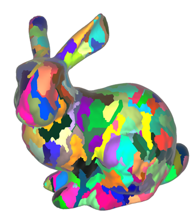
Bunny meshlets, from NVIDIA’s introduction to Mesh Shaders
Nanite uses the METIS library for its cluster generation. For my reimplementation, I am going to try to use Meshoptimizer which has utilities for meshlet creation, and mesh simplification, which will be useful in the next section. But if need be, I might use METIS too.
Once I can split a mesh into meshlets, I want to attempt to convert a mesh and render it through the visibility buffer. At that point, no LOD selection will be ready. Therefore it will just be a regular mesh, rendered meshlet by meshlet.
Note: for now, I do not plan on using mesh shaders but they may arrive later.
LODs generation
Once the initial mesh has been split into clusters, the goal is to create a hierarchy of new clusters, which represent different LODs. According to the Nanite presentation, the process is:
- Group adjacent clusters by groups of ~4
- Find the boundary of the adjacent clusters
- Simplify the interior vertices (boundary are locked vertices)
- Split the grouped clusters into 2 new clusters for the next level in the hierarchy.
- Note: the 2 clusters must have the same parameters to decide when to transition LOD level, otherwise cracks between elements may appear. (ie you need the same bounding sphere & projection information)
- Repeat until you have a single cluster
At the end of this step, I should have a graph of clusters, where the root is the lowest LOD mesh for the entire mesh, and each child of each node is a cluster of higher LOD.
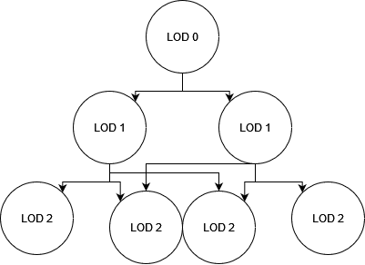
Hierarchy of clusters. Each node is a cluster for a given LOD. Some LODs are shared between clusters to avoid locked edges. LOD 0 is the least detailed in this diagram.
LODs selection
Once you have a hierarchy of clusters, you can “easily” find which one to draw based on the position of the clusters relative to the camera. This is what Nanite calls the “cut”.
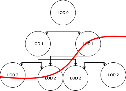
The cut, clusters on the line are drawn, other clusters are discarded.
- Project the bounding sphere of the cluster to find its approximate area on screen.
- If the area is below the threshold and its parent too, discard the cluster. This cluster is too detailed.
- If the area is below the threshold but its parent is above, draw this cluster.
- If the area is above the threshold and its parent too, discard the cluster. This cluster is not detailed enough.
- If the area is above the threshold and the current cluster is a leaf cluster (no children), draw this cluster? Maybe we want to discard clusters that are too small, but this may create issues for models composed of many small clusters. For example: a wall made of individual bricks. Seen from afar, the individual bricks might be tiny, but discarding all clusters will lead to the wall disappearing.
This way, you select the least detailed LOD that is visually identical to the original model for a given viewpoint.
The Nanite paper goes into details to do this properly with multithreading and on the GPU, but that’s a problem for far-future me.
Software rasterization
I am not going to go into details for now, software rasterization is well documented and Nanite seems to implement a basic version from what I understood.
Going further
There are many aspects I have not mentionned in this post, but virtualized geometry also enables to do fine-grained occlusion culling.
I also did not talk about how I expect the choice between regular meshes and virtualized geometry to be done inside my engine (if I don’t replace all opaque rendering with Virtualized Geometry).
Conclusion
There are many parts to implement before reaching a point where a Nanite-like system is available in my engine.
I am going to start soon, first with the Visibility buffer.